We use one of several proprietary pipe stress analysis programs. Be cautious of over-constraining 4-point stands.

Focus Pipe Support Calculation Focus Group
When considering re-using any stand design determine if old engineering notes exist andor if a new engineering note should be written andor if the design is robust andor functional.
. It should be noted this application is a training tool and must not be substituted for a finite element software. P t s max A 1 Where P t maximum pulling force lb s max maximum allowable tensile stress 1000 psi A cross sectional area of pipe in2. M3hr - Flow req.
When each end is fixed theoretically k 05 but 065 is the recommended value. - adequacy check of existing foundation for PS-01 - new foundation design for pipe supports PS-02 03 04 - new concrete pipe supports design PS-05 to PS-10 PS-29 to PS-32 and PS-33 to PS-35 All Pipe support foundations are checked with the latest loads as per Appendix II. Pressure Drop Due To Pipe workxls 10Piping File Repository GIVEN.
The structural adequacy of the subject Legibil 8Wc ity evaluated and peydfor aUe 9305280306 930522 PDR ADOCK 05000390 Signature p A PDR C Microfilm and store calculations in RIMS Service Center. M3s - Velocity ms - Pipe Dia. 32 Pipe Support Structure Weld Bolt Sizing Criteria 75 Design of pipe supports for Salem is in accor-dance with ANSI B311.
When a column is hinged at each end k 10. A 312 TP316L t. The calculation is applicable only for uniform pipe without any attached concentrated weight such as a valve.
Calculation will allow you to estimate the head loss pressure drop in a pipe with a nice clean internal surface. Scope of work for Foundation calculation consists of. When one end is fixed and the other is free it is a cantilever and k 20.
Determine Friction Factor f assuming completely turbulent flow f 114 2 log10De-2 2. Civil Engineering hydraulics design calculation software - covers calculations for hydrology open channels stormwater run-off culverts gravity sewer sanitary and storm sewer. Alternatively a more comprehensive FE analysis can be used.
Pipe Support Calculator - Quickly calculate 8 to 128 ordinates for custom cut pipe to attach to the back of a 90 degree fitting. Support Spacing by Bending Limit L1. Calculations done by spreadsheet 1.
M - Corrected velocity ms - Static Head m - Density. To facilitate this instruction an Excel workbook program Pump_Pipexls has been developed that will perform flow system calculations and pump selection analysis. Considering deadweight thermal and dynamic effects system stress levels and equipment loadings are calculated along with loads and movements acting at the support positions.
This pipe support spacing calculation was developed based upon equations contained in section 62 of Pipe Stress Engineering published by Peng Engineering. Bergen Pipe Supports can offer pipework stress analysis to ASME B311 B313 and other design codes. Use of trunnions attached to full ring wear plates.
For complete background information on the derivation of the formulas refer to the article. Here is a listing of all the worksheets included. M - Corrected pipe dia.
B1314161819202122 according to the design of the system - Use Pipe Chart Dimensions Weights-example 40s Std 3. Allowable Pipe Support Span Calculation. Enter in green cell.
Components used in pipe supports rods u. OR1ONiAL This calculation verifies pipe support. Document design calculations for pipe support referenced in calculations title.
For calculations on a 4-point stand assume that the load is distributed on only 3 points. Pipe to pipe distance Larger flange radius larger pipe insulation thickness 25 mm Gap Insulation thickness of other pipe another pipe radius Refer the below figure for better understanding of formula- Fig. Xls g Pipe_SI_cS_Dint_dn_sch Pipe_SI_SS_Dext_dn Pipe_SI_SS_Dint_dn_sch Pipe_SI_SS_Thickness_dn_sch m - bar mm 10S dn in 5S 40S 80S-N t dn E 1 2 Sch P MPa sch Nominal pipe size NPS W Y Mpa Pipe thickness Maximum bending stress PD 2SEW PY Material.
Pipe Support Design Calculation Excel. Enter design variables for pipe system. Input Pipe Outside Diameter mm Input Wall Thickness mm Input Allowable Stress psi Use 5000 psi for CS pipes up to 400F Input Modulus of Elasticity ksi Use 27700 ksi for CS pipes up to 400F.
Calculate V and Q using the final value for f calculated in step 2. - Input Values as Fractions. Allowable stresses for pipe support material are taken from this code for all normal operation.
Outer diameter pipe wall thickness specific gravity if known length between supports and shield arc shown in green cells. Thermal design or HVAC are piping system calculations coupled with the required pump calculations so as to appropriately select a pump. This file was corrected according comments from Derek Marshall Rev.
Pulling forces and lengths information is desirable for design and estimating purposes. It is not applicable for the overhanging span either. Pipe to pope distance calculation formula So B 272125257584 581 585 mm Similarly C 17775257557 409 410 mm.
The Pipe Support Calculator is designed for all Pipefitters weldersfabricators to eliminate the time it takes to calculate normal piping calculations. Buried Pipe Calculator excel application has been designed as a training tool to help users to calculate stress and strain requirements and their corresponding criteria for both restrained and unrestrained sections of a buried pipe. Welcome to Aquatherm Australia Web.
RJT M 300 lb. Diameter is the greater of the 2 impacts. That is the case I assumed for your pipe support fixed at the base and free at the top which I took to be BOP.
Created on 05 July 2011. Maximum span between pipe supports for a given maximum tension stressxls Determination of the length between pipe supports by the method of the Maximum tension Stress due to bending and internal pressure. In general head loss is higher in small diameter pipes and long lengths of pipe.
Pressure design thickness ksi P. The maximum force that can be applied to a pipe on level ground can be determined by the following formula. CE CALC - Hydraulics Calculator v20.
Pipe support trunnions are usually calculated using the formulas included in Design manual Piping mechanical from the M. Check on whether the given flow is completely turbulent flow 3. Every single trunnion should be calculated individually.
Piping Tools And Thermodynamic Excel Functions Add Ins

Calculation Of Pipe Support Pdf Beam Structure Bending
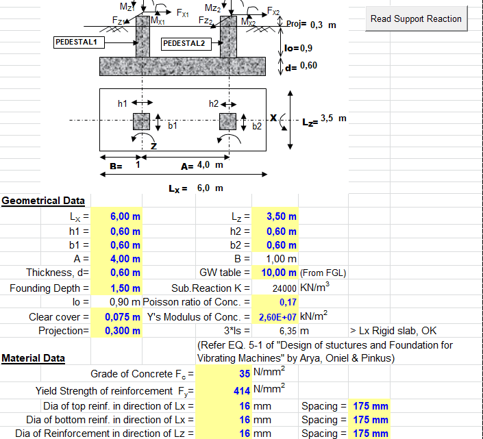
Combined Foundation For Pipe Rack Spreadsheet
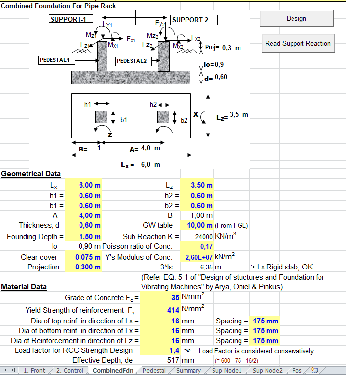
Combined Foundation For Pipe Rack Spreadsheet

Calculation Of Pipe Support Pdf Beam Structure Bending

Download Pipe Support Calculation Xls Seltrecmalop1987のブログ

Www Pdfstall Online Total Piping Design Calculations Spreadsheet Most Important Sheet
Pipe Calculator Spreadsheet
0 comments
Post a Comment